
SECURITY CAMERA PLANNING GUIDE
How to plan a security camera system
Start with where people can enter and what you need to see there. Camera placement comes first; the equipment list follows the coverage plan.
This guide focuses on a home or small property's camera system. Cameras are one part of security alongside locks, lighting, access control and, where needed, an alarm. A map helps organize the design; a walk around the site and recorded test footage establish whether it works.
1. Mark every entrance and vulnerable area
Walk the boundary, then the building. Mark the front door, back door, patio doors, garage doors, side gates and any other usable entrance. Add accessible ground-floor windows, basement access, secluded side passages, sheds, delivery areas and equipment or vehicles you want to watch. Include the route a person takes to reach each opening, not just the opening itself.
Make a small coverage schedule: location, viewing goal, proposed camera, obstruction, cable route and test to perform. Give every entry point an explicit decision. If an area cannot be covered, record the gap and consider a different mounting point, lighting, an additional camera or another security measure. Do not let a large colored cone hide an unresolved problem.
- Front entrance: see an approaching visitor and the doorstep or parcel area.
- Rear and patio doors: see the approach even when patio furniture or an open door changes the scene.
- Side gates and passages: cover the route between the street and rear yard, including the gate opening.
- Garage and driveway: distinguish a general vehicle overview from the closer view needed at a person or vehicle access point.
- Accessible windows and outbuildings: look for concealed approaches, vegetation and places outside the main entrance views.
For each area, write a specific objective such as “record a usable face view at the side gate” rather than “watch the yard.” Overview and identification are different tasks; image detail, angle and conditions all affect the result. Axis explains this distinction in its image-usability guidance.
2. Place cameras around the viewing goals
Entrances: cover the person and the approach
Start with a mounting position that sees someone approaching the door rather than only the top of their head when they arrive. Check both directions along the path. A porch pillar, recess or hanging decoration may block a useful view. Record where the face needs to be visible and check that exact spot with the intended camera.
A doorbell can provide a useful entrance view, but test its framing for visitors, parcels and the direction of approach. Add a separate approach camera when those needs do not fit one view. See the doorbell camera placement guide for planning limits and wiring notes.
Corners and side paths: check the blind spots
A corner is a possible mounting point, not proof of full perimeter coverage. Walk close to the wall as well as along the center of the path. Check the area immediately below the camera, behind rainwater pipes, around corners and under overhangs. Where two views meet, plan enough shared coverage to follow movement between them and verify that overlap on site.
Driveways, garages and backyards
Give the driveway entrance, garage access and pedestrian approach separate entries in your schedule. A yard overview can explain where somebody went while an entrance camera provides a closer view. Do not assume a wide driveway camera will also capture readable moving plates at night; that is a separate design and testing task. Our driveway and garage guide helps separate these goals.
For a rear yard, include the rear entrance and gate before adding general garden or pool views. A pool camera is for observation; it does not replace supervision or a pool safety system. Keep indoor cameras to agreed areas such as an entry hall or garage and avoid unnecessarily recording private living spaces or neighboring property.
Mounting height: test the angle, not a universal number
Choose height together with the target distance, lens and mounting constraints. A high overview camera may give a poor face angle close to the wall. A lower position may be more exposed to tampering. Follow the model's installation instructions, record the proposed height in your plan, and test it before drilling permanent holes. Manufacturer analytics may have their own placement requirements.
3. Check field of view, obstructions and night conditions
A wider view includes more area but spreads the image detail across that area. On the same sensor, a shorter focal length generally gives a wider view; the actual sensor and lens combination matters. Use the manufacturer's field-of-view specification where possible. Compare our 2.8 mm vs 4 mm lens guide and coverage-width calculator, then verify the image at the intended target distance. Axis's lens reference explains the optical factors.
Draw the intended viewing direction in the Mapper, then list anything the overhead map cannot establish: fence height, foliage, parked vehicles, stairs, porch ceilings and walls. Coverage cones are planning estimates. They do not simulate walls, certify identification or prove visibility through a building.
Visit in daylight and after dark. Note bright doorways, deep shade, headlights and nearby lights. Check recorded moving people, not just a sharp still image. A night view that shows the whole yard may still fail to show useful detail at the gate. Test the chosen camera's night mode and lighting at each critical location; see Axis's guidance on environmental conditions and usable images.
4. Turn the survey into a map layout
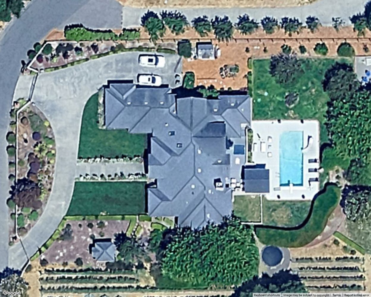
In CCTV Mapper, locate the property and add devices at proposed mounting points. Name each camera by its job, such as “Side gate approach,” and record the height and target area in notes. Use colors consistently: one for outdoor approaches, another for indoor views, or matching colors for camera groups.
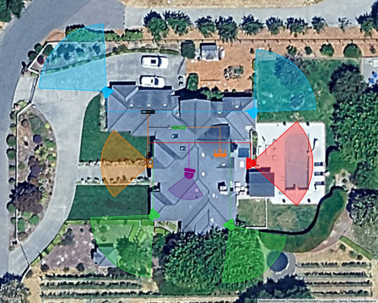
Here the camera and wired-doorbell connections return to a proposed PoE-capable NVR. The access point connects to the PoE switch, with the NVR also linked to that switch. Confirm device compatibility and port capacity before using this arrangement. Interior cable routes and room positions must be checked; the satellite image only shows the roof. The 10-device example may exceed your account's device allowance.
5. Plan cabling, power and recording
Choose a network arrangement you can actually install
Two common arrangements are cameras connected to a compatible PoE NVR's camera ports, or cameras connected to an external PoE switch with a recorder on the network. A recorder without PoE ports does not power cameras. An access point normally belongs on the network switch, not an isolated NVR camera port. Check the specific recorder's network design and supported cameras.
For each wired device, record the source port, cable route, approximate length and termination location. Draw routes along feasible building paths rather than across open space merely because the line is shorter. Include vertical rises, bends, service loops and the route through the building when measuring. Choose cable and protection appropriate to the installation and have electrical or building work handled as required.
Check both available ports and total PoE budget, as well as each device's required PoE standard and maximum demand. Include access points and other powered devices in the count. The PoE calculator provides a first estimate; its reserve does not replace equipment specifications. A Wi-Fi device still needs power, and a planned access point location does not prove wireless performance. Test the actual link at the camera position.
For doorbells, confirm whether the particular model uses PoE, a transformer/chime arrangement or another power source. Mapper connections currently represent network planning; they are not a transformer or mains-wiring design.
Choose what to record and how long to retain it
Write down whether each camera records continuously, on events or on a schedule, and how many days you want available. Estimate storage from camera count, average bitrate and recording hours using the recording-storage calculator. Measure actual usage after installation before relying on a retention target. Review recorder channel capacity, supported formats and incoming bandwidth as well as disk space.
If you plan to use a PC recorder, read planning a Blue Iris camera network. Choose a protected, accessible location for the recorder and network equipment, and document any backup-power requirement. Protect administrative access and use the manufacturer's supported secure remote-access approach.
6. Test the plan before calling it complete
Use the coverage schedule as an acceptance checklist. Temporarily test each proposed view safely, then repeat after final installation. Review saved recordings on the recorder, not only the live camera preview.
- Walk every approach: front, rear, side gate, garage and accessible windows. Include the edges of views and positions close to the building.
- Check the intended detail: can you see what your objective requires at the actual location, in motion and in both directions?
- Repeat at night: test with normal lights, headlights and the camera's night mode.
- Change the scene: open doors and gates, park vehicles in their usual places and check likely vegetation growth.
- Verify recording: confirm time settings, playback, event behavior, retention and recovery after a controlled restart.
- Document the result: adjust camera positions and cable routes in the map, note unresolved gaps and save the final project.
Members can use the export workflow to document the map for installation. Keep the equipment list and notes current when a camera moves. Recheck views after landscaping, lighting or building changes. A useful plan describes the system as installed, not just the first idea.
Route cables around walls and corners
Connect the devices in the Mapper, then choose Edit route beside a connection or click its cable on the map. Drag a midpoint handle to add a bend and move the bend along your proposed route. Select a bend to remove it, or use Straighten to start again. Apply the route when you are ready.
Saved bends appear on shared maps and map exports. Cable estimates follow all segments and retain the existing one-metre connection allowance; the equipment schedule can add a separate percentage allowance. Map distances are horizontal estimates: account for risers, drops, service loops and actual installation conditions on site.
For installers: turn the layout into a client handoff
Use the map during the site survey to agree on what the customer wants to see at each entrance and vulnerable area. Describe the intended outcome in plain language: a visitor at the front door, activity along the side passage, or an overview of the yard. Explain any limits before quoting the equipment.
- Present the proposed design: share a layout link with the client and walk through camera positions, color groups and planned connections. Confirm the link shows only information you intend to share.
- Agree on scope: record the selected views, equipment, cable routes, assumptions and excluded areas in your proposal. Obtain approval through your normal quoting process; a shared map is not a signed acceptance.
- Track site changes: update the plan when a mounting point or cable route changes. Discuss changes that affect coverage or cost before completing the work.
- Demonstrate the result: review recorded day and night views with the client against the agreed coverage goals.
- Deliver the installed layout: provide the final map, equipment and cable schedule, relevant notes and maintenance instructions. Keep passwords and access credentials out of shared maps and handover PDFs.
CCTV Mapper helps explain a system visually to clients who do not read technical drawings. Use its sharing and export workflow alongside your quotation, commissioning checklist and customer documentation.
Common security camera planning questions
How many cameras does a house need?
There is no universal count. List the entrances, approaches and vulnerable areas first, then work out which objectives one camera can reliably cover. Add cameras for remaining gaps instead of choosing a kit size and forcing the layout to fit it.
Should I use one wide camera or several narrower views?
Choose by purpose. A wide overview can show activity across a space; closer views can address particular entrances. Test whether the resulting recordings meet both needs. A larger coverage cone alone is not evidence of a better design.
Can a map tell me exactly what a camera will see?
No. Mapper helps organize positions, directions and estimated connections. It cannot verify walls, mounting height, night performance or usable image detail. Check the camera's specifications and test on site.
Where should I start?
Start at the entrances. Make one clear viewing objective for each, then work outward to approaches, concealed areas and general overviews.
Put your camera placement plan on a map
Mark the entrances, add cameras at realistic mounting points and connect the network equipment. Keep your survey notes alongside the layout.
Open Mapper Read the quick startCCTV Mapper product guide · Updated October 16, 2026. Technical background: Axis: Quality with a purpose, Lenses in surveillance, and Site survey considerations. Example placements and the checklist are illustrative planning guidance; follow equipment instructions and applicable installation and privacy requirements.